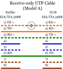
The goal of a receive-only UTP cable is to generate several errors on the sniffer's Transmit Data Signal. This avoids the remote device recognizing any data sent by the sniffer but at the same time keeping the link up.
In the following models, a few examples of sniffing-cable preparation are explained. All of these cable models are designed to work attached to a hub (half-duplex mode).
It is important to emphasize that these models are not designed to work with a switch because in working with a switch they will not be very useful. A switch makes fowarding decisions using hardware addresses, and does not forward the traffic to all ports (unless it doesn't have the destination address in its switching table). It would require using ARP Spoofing techniques or something similar to intercept the conversations in the switch, and we would never receive all the traffic like we would with a hub. However, there are switches with span/mirror ports. These special ports receive the traffic of specified switch ports that the switch administrator nominates, acting like ports on a hub, but they can be overflowed if they receive more traffic than the one(s) they support. See section 4.2 `Taps vs. Span Ports' for more details.
As we can see, this model uses a capacitor to insert high levels of errors in the line. [2]
Capacitor acts as a high-pass filter. According to the 10Base-T signal, the capacitor's pass band should be above 5Mhz frequency. That is the minimum frequency using Manchester encoding (with an alternate sequence with `0s' and `1s').
We can calculate the capacitor's value by the following method:
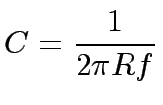 |
In a 10 Mbps Ethernet, the frequency is of 5Mhz, and the resistance is of R = (Rsource+Rload) = 200 ohms. Therefore, the capacitor's value should be of 150p(F).
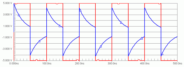
This method should introduce enough errors into the Transmit Data Signal, but keeping the link active at the same time. The figure 6 represents a simulation of the appearance of the output signal (blue, triangles), in relation to the original one (red, squares). The loose of power of the original signal, caused by the capacitor, can make it undetectable by the hub. Greater capacitors could be used to reduce this effect.
I tried this model in an Ethernet LAN environment, attached to a 10/100 Mbps hub, but the link was not active.
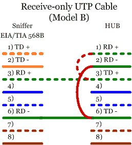
An easier way to implement a sniffer cable is by connecting pins 1 and 2 (pair number 1) on the LAN side to pins 3 and 6 (pair number 2) on the same side respectively. [3]
This method returns any signal sent from the LAN to itself, acting like a hub. This model worked on a LAN with a 10/100 Mbps hub without problems.
Model B can be improved just by changing the order of the connections.
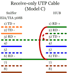
Figure 8 describes the wiring schemes for Model C. If we connect pins 1 and 2 of the LAN side to pins 6 and 3 respectively, the signal returned to the LAN is inverted. This method ensures the link remains up and should introduce sufficient errors on the Transmit Signal to make it incomprehensible. As with Model B, this model also works. However, this method is theoretically the best one because it modifies the signal returned to the LAN.
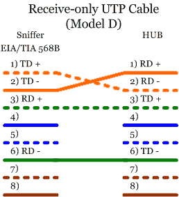
The last model is even easier than the three previous ones. It just changes the order of the Transmit Data Signal pins.
The signal sent from the sniffer is inverted, making it incomprehensible when received on the LAN side of the communication, but it ensures that the link stays up. Unfortunately, the hub used in the tests was able to recognize the signal sent by the sniffer.
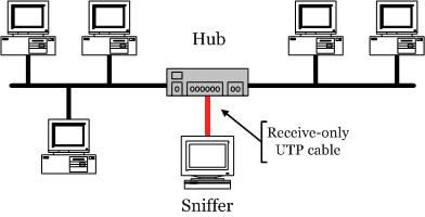
The typical scenario for using these cables is described in figure 10, plugged into a hub between the network segments to analyze. It does not matter that the LAN is 10Base-T or 100Base-TX if we use a hub that supports the required speed. The disadvantage is that they can only work in half-duplex mode. In fact, the maximum efficiency of a hub is about 40% of the ideal speed.