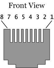
As mentioned previously, this article is related to UTP cables, with RJ45 connectors. Before explaining the various sniffer types, it is fundamental to understand the standard wiring schemes. Figure 2 shows the pinouts of a RJ45 connector.
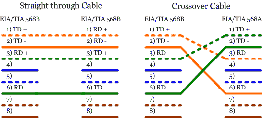
Figure 3 describes the wiring schemes of straight through and crossover cables. Straight through cables can be used to connect a host or a router to a switch or hub. Crossover cables may be used to connect the following: host to host, hub to hub, switch to switch, switch to hub, router to router. The models of sniffing cables in this paper are based on straight through cables, but the crossover cables can be also used if the sniffer's transmit signal is modified in the same manner.
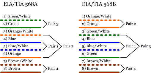
There are eight wires grouped into four coloured pairs. The pairs are twisted to reduce the effects of noise and interference. Each pair has a different twist ratio that can affect the signalling at higher speeds, so it becomes important to follow the colour codes. Note that pairs 1 (blue) and 4 (brown) are not used in 10Base-T or 100Base-TX Ethernet. All eight wires are used for 1000Base-T Ethernet. [1]
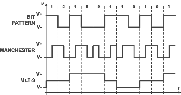
Ethernet LANs use digital signals to share data among network devices. 10Base-T uses Manchester encoding to transmit the signal: transition occurs in the middle of each bit period. Two levels represent one bit. A low to high transition in the middle of the bit represents a `1'. A high to low transition in the middle of the bit represents a `0'. There is no DC component. It uses positive/negative voltages.
100-BaseTX uses 4B/5B encoding, where each 4-bit nibbles is being transferred encoded as 5-bit symbols. The signalling model is a three level multi-level technique called MLT-3.
|